Pressure Vessel Design
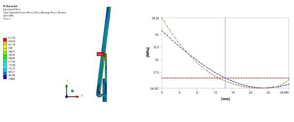
Stress Analysis of Nozzle Shell Junction

Project Definition
Provide Finite Element Analysis for shell to nozzle junction for nozzles N1 and N2 as per ASME Sec. VIII Div. 2, part 5 for vessel of Inlet Black powder filter package for BCGS-5.
Design Inputs
• Maximum Allowable Working Pressure (MAWP): 6.9897 MPa:
• Design Temperature: 73.89 °C
• Corrosion Allowance: [Please provide value if available]

")


Project Definition
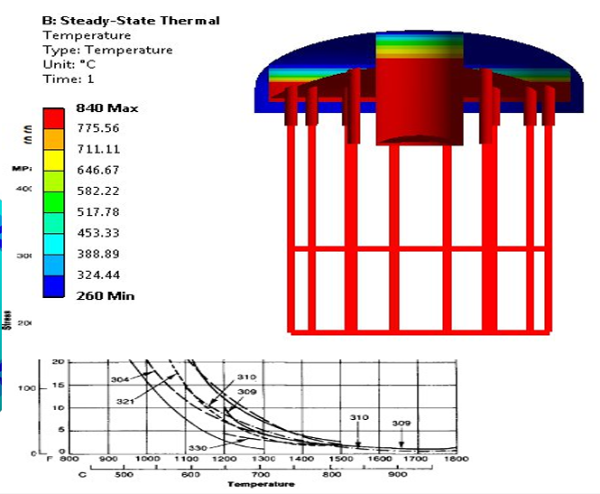
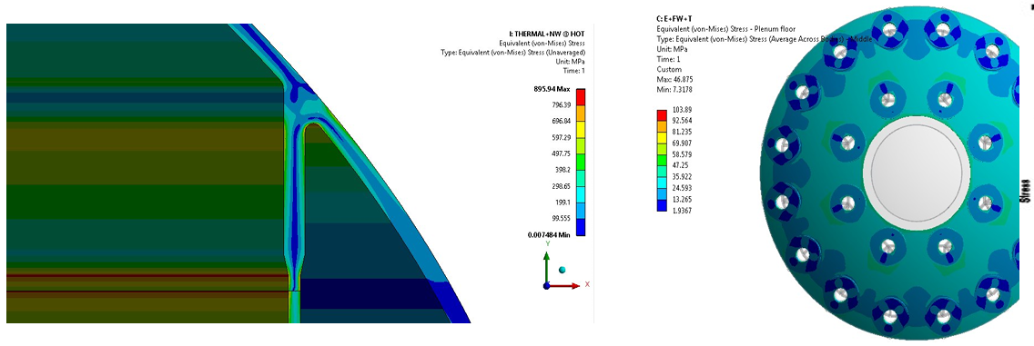
The analysis specifically focuses on the design of the head/plenum junction and the bimetallic weld between the plenum’s inner and outer skirts. Due to severe temperature gradients, these areas are subjected to significant thermal stresses. Additionally, stresses arise from vessel design pressure, plenum pressure differentials, the self-weight of the plenum, and the dead weight of the cyclone.
Design Inputs
Normal Operating Weight + Design pressure + thermal loading
| Load Cases | Hours | Temperature (C) | Load Factor |
|---|---|---|---|
| Normal | 100,000 | 770 | 1.00 |
| Flooded | 10,000 | 770 | 1.41 |
| Upset | 100 | 840 | 1.00 |
Creep and and Fatigue Analysis of Tertiary Cyclone Vessel
Dewaxing Heat Exchanger fatigue analysis

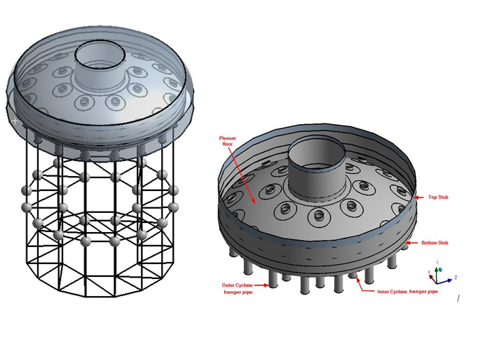
Fourth Stage Separator (FSS)–Thermal-Structural Couple Analysis

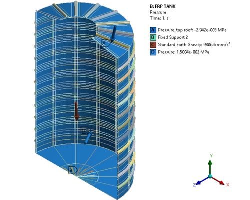
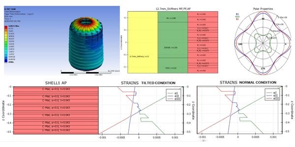
FRP Tank- Development of FEA Methodology

Project Definition
This project involved calculating the fatigue life of a heat exchanger. Fatigue life was determined using ASME Section VIII, Division 2, Part 5. The stress amplitude required for the fatigue life calculation was obtained through finite element analysis. Fatigue life for different subassemblies of the heat exchanger was calculated separately and then compared with the design number of cycles.
Description
The project was executed using ANSYS. Transient thermal loads were applied to each partition compartment. Thermal loads from the first pass through the exit of the sixth pass were calculated using linear interpolation between the thermal loads at the first pass and the exit of the sixth pass.
Key Deliverables
- Designverification as per code requirement


Project Definition
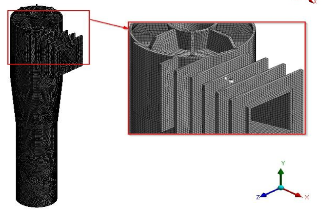
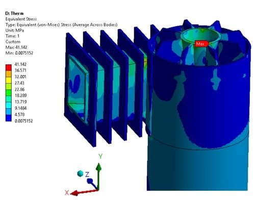
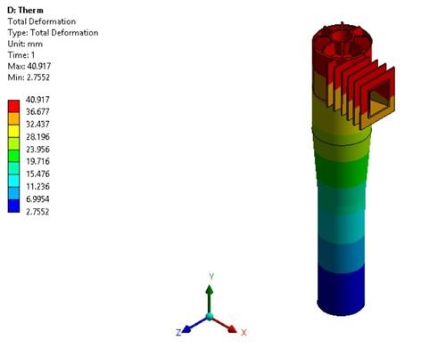
Performed the design of the Fourth Stage Separator for design pressure, self-weight, and thermal loads at 840°C. All work was conducted in accordance with the requirements for a tertiary cyclone vessel and ASME Section VIII, Divisions 1 and 2. The assessment was based on results from three-dimensional steady-state thermal and linear elastic stress analysis of the assembly, carried out using finite element software. The project was executed using ANSYS, considering load cases including Normal Operating Weight, Design Pressure, Thermal Loading, Seismic Loading, and others
Project Definition
Design and analysis were performed for a Fiber Reinforced Plastic (FRP) tank. The tank contains liquid head and is subjected to internal pressure. An optimum design was developed to achieve minimum thickness with optimal volume fractions of fibers, ensuring the required strength under the specified working conditions, in accordance with ASME RTP-1 code
Design Parameters
| Analysis condition | Part | Internal Pressure (MPa) (g) | Design Temperature (°C) |
|---|---|---|---|
| Design | Tank Shell | 0.015 | 60 |
| Design | Tank Roof | 0.003 | 60 |